StrydSense™ is a non-invasive electromyogram based control system that listens to the users’ body. Signals recorded by the sensor are digitally processed on-board to suppress noise and unwanted artifacts. StrydSense™ features a four-band graphic equalizer to tailor the system’s sensitivity for every muscle.
Principles of Digital Signal Processing
-
Muscle Action Potential
Bioelectric signals are generated and transported by nerves to muscle…Read More
-
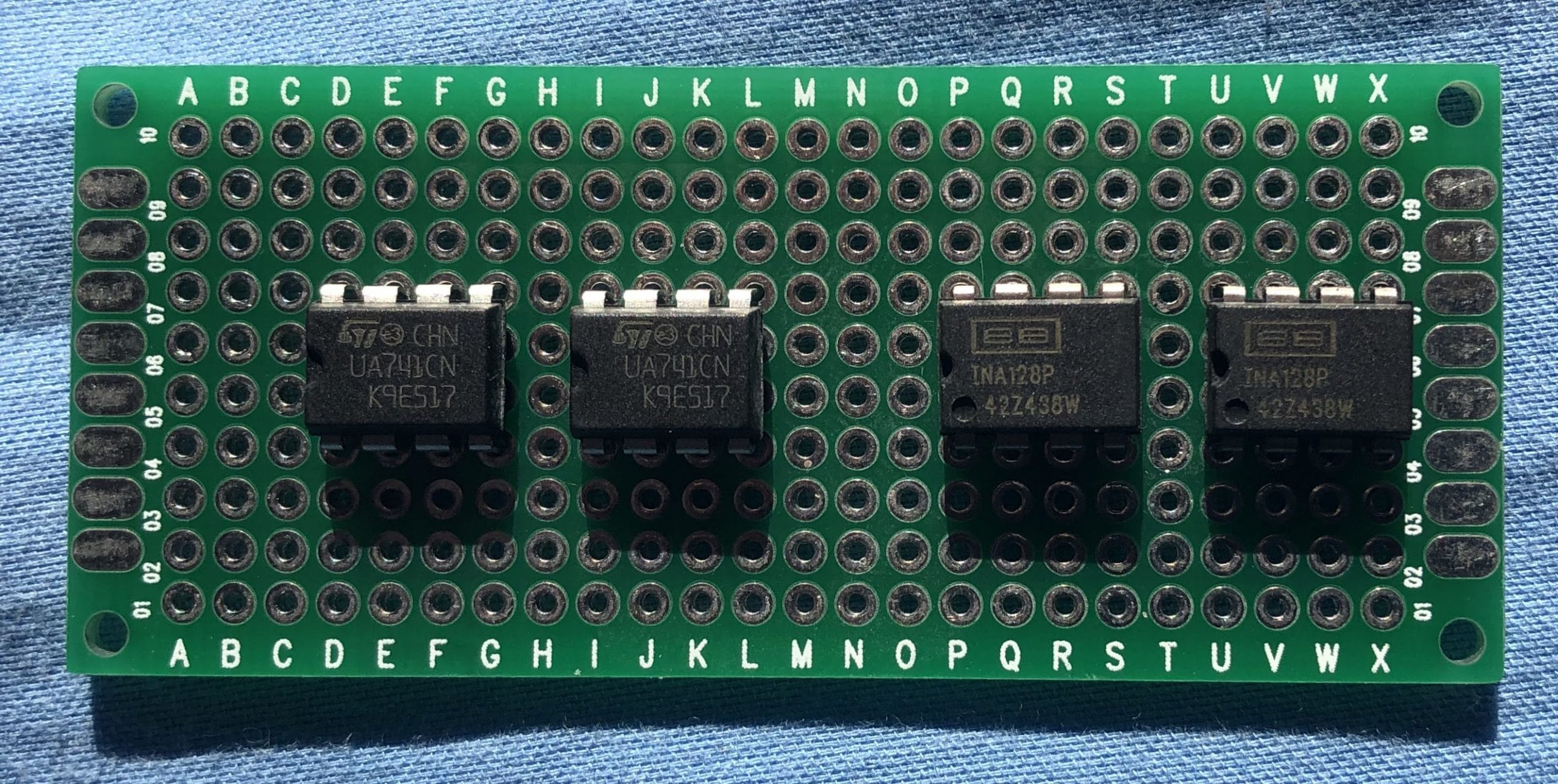
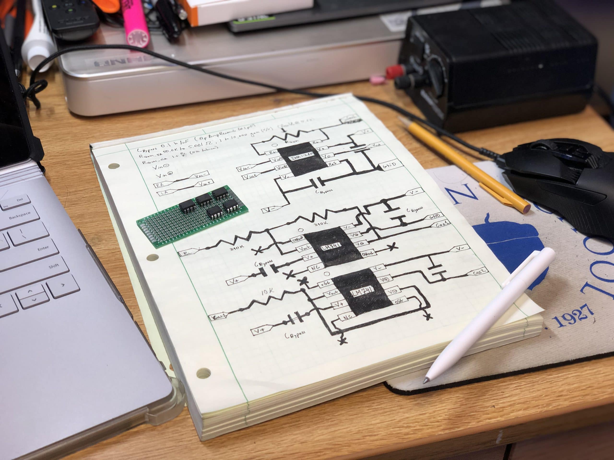
Analog Front End
Bioelectric signals are amplified from 1-10 mV to 1-3300 mV.…Read More
-
Analog Digital Converter
The acquisition and conversion of a continuous-time analog signal into…Read More
-
Time-Frequency Transform
The Fourier transform is central to digital signal processing because…Read More
-
Digital Filtering
Visualizations of the early 4-band equalizer frequency response. IIR BiQuad…Read More
Revision History
Scroll down to learn about the process
Revision 2 – STM32F4429I-DISC1
Working:
- ADC Input, DAC Output
- USB Virtual Serial COM
- 50 and 60 Hz Power-line Filters
- 4-Band Equalizer
Work in Progress:
- Direct Memory Access
- ADC transfer to RAM performed by DMA controller.
- Bypasses CPU involvement
- Interrupt based multitasking, no threading needed!
- Zero-Phase IIR Biquad Filters
- Filter Input passed through filter.
- Filter Output reversed and passed through filter.
- IIR BiQuad filters order reduction by 50%
StrydSense™ is now running on the STM32F429I microcontroller. This is a massive upgrade in terms of processing power with slight impact on total power draw, but I haven’t really looked into power optimization settings yet nor will I for the scope of this project. The STM32F429I features a phase-locked loop (PLL) to lock the processor clock speed. This closed-loop control system accurately maintains high frequencies. Although this frequency can still be affected by the temperature of the crystal, its overall variance is negligible compared to the 6% stock inaccuracy of the MSP430 chips.
Clock and Timer Configuration
However, the learning curve associated with developing on ARM Cortex-M4 is steep. This became immediately apparent as I worked on configuring the pin assignments. The Integrated Development Environment has a lot of tools to automatically generate code. You need to configure settings for pin assignments through the GUI interface otherwise edits made in sections for autogenerated code get deleted the next time a change to the pin assignments occurs – a lesson learned only once.
After configuring the desired clock speeds and timer settings in the STM32CubeMX design interface, code was automatically generated. This was fairly pain free.
Initial ADC/DAC Configuration
Now that timers are generating interrupts at the correct time intervals, the challenge becomes using the interrupt to perform the desired task: acquiring data!
I have attached my painfully verbose ADC callback function. The machine’s initial state is “DoNothing” which updates to “StartFiltering” when the ADC has completed filling the array with fresh data.
void HAL_ADC_ConvCpltCallback(ADC_HandleTypeDef* hadc){
	// If the interrupt on ADC1 on pin PA2
	if(hadc->Instance == ADC1){
		// Red Led on PG14 is Low during filter process.
		HAL_GPIO_TogglePin(GPIOG, GPIO_PIN_14);
		// Acquire sample from ADC
		value = HAL_ADC_GetValue(&hadc1);
		// Save value into Value_ADC_Input array
		Value_ADC_Input[SAMPLE_COUNT] = value;
		// Increment Counter
		SAMPLE_COUNT++;
		// When sample count is equal to the length of the Value_ADC_Input Array defined by "TEST_LENGTH_SAMPLES"
		if(SAMPLE_COUNT == TEST_LENGTH_SAMPLES){
			// Stop Timer and ADC Sampling
			HAL_TIM_Base_Stop_IT(&htim2);
			// Reset Counter
			SAMPLE_COUNT = 0;
			// Update State
			Process = StartFiltering;
}}}
Main Function
The main function beings with automatically generated initialization code for the ADC/DAC and Peripherals. I created an infinite loop to call the filtering function, post-process the data, and then output via DAC.
The intended function of the post-processing code was to scale the signal and prevent saturation of the 12-bit DAC. In the end, these functions were well meant but poorly thought out as empty signals would be scaled to fill the full 12-bit value range.
Filter Functions – ARM
Filter Design – MatLab
Power Line Filters
-
-
- Filters coefficients are saved as single precision floating point numbers or fixed point numbers. While converting to either format may not seem significant, the conversion is lossy which means that the a filter quantized in single precision floating point may not be represented exactly through fixed point representation. This has proven to be a thorn in my side more than once because example code for ARM CMSIS DSP functions can use either datatype at the expense of being consistent with that data type throughout the process. This means when I transplant fresh filter coefficients into example code, a substantial amount of debugging has to happen before I can actually confirm that the code works and that the filter coefficients are correct.
- I implemented 50 Hz and 60 Hz filters as separate 10th order Chebyshev Type I, Biquad IIR Bandstop filters. I designed the filters to provide 60 dB of attenuation in the 49 to 51 Hz and 59 to 61 Hz ranges.
-
Signal Equalizer/Gain Adjustment
-
-
- I struggled really hard to find a way to implement an equalizer. This is in part because designing a solution in MatLab or Simulink does not necessarily translate to a functional design at a microcontroller level. My process involved three stages: (1) performing multiple FIR filter operations on a signal stored in memory to isolate specific frequency bands (2) multiplying these isolated bands by scalar coefficients to control the band gain (3) combining these output signals together to generate a final output. This is not only seriously memory and CPU intensive on a 168 Mhz MCU but also literally lacks CMSIS DSP functions to help accelerate the process.
- I stumbled across an example for how to implement a graphic audio equalizer. Although, the sampling rate is substantially higher than the range I am working with the procedure is much more elegant! Based on the “gain” value stored in memory for each band, the function pulls the relevant filter coefficients from a table of all possible filter coefficients and then applies the first filter stage to the signal. The output of this stage is fed to the next and so forth until the equalized signal is output.
- I wrote a MatLab function to generate these coefficients much more quickly and with convenient commenting because I am still having a hard time identifying non-catastrophic problems in microcontroller code (the ones that don’t throw compile errors but result in non-desired results).
-
Filter Design – STM32
Developing firmware on the STM32 has been a steep learning curve. With the help of several tutorials, I managed to make a lot of headway in configuring the ADC input and DAC output. Simulink, with a handful of additional expansion packs, can generate optimized ARM Cortex-M code that can leverage the CMSIS interface with the DSP hardware. This gave me a head start in implementing filters, but it ended up being a lot of work to configure Simulink to generate code specific to my microcontroller. Trying to integrate the working code proved to be a frustrating experience. I stopped trying to hybridize the Simulink code and simply studied it with the Keil IDE CMSIS documentation. This was the breakthrough I needed because I was able to follow the examples for Biquad IIR filter implementation and develop my own configuration.
My working 50 and 60 Hz IIR bandstop filters can attenuate input signals by a minimum of 60 dB at these frequencies. I increased the width of the notches to accommodate for minor frequency shifts due to sampling and power line variance and am attenuating in excess of 80dB at the center of the notch.
The FIR filter I intended to implement would have provided an equalizer-like behavior to tune the signal for different users. Instead of using a single filter, I discovered an example in the Keil IDE CMSIS documentation for a graphic equalizer for +44 kHz audio. This is implemented with Biquad filters, fixed point coefficients, and lacks a referenced Matlab script. Although the difference between fixed point and single precision numbers isn’t always dramatic, it can affect filter profiles and I don’t have the technical skill to predict the filter deformation yet, so I am stick with single precision floating point coefficients.
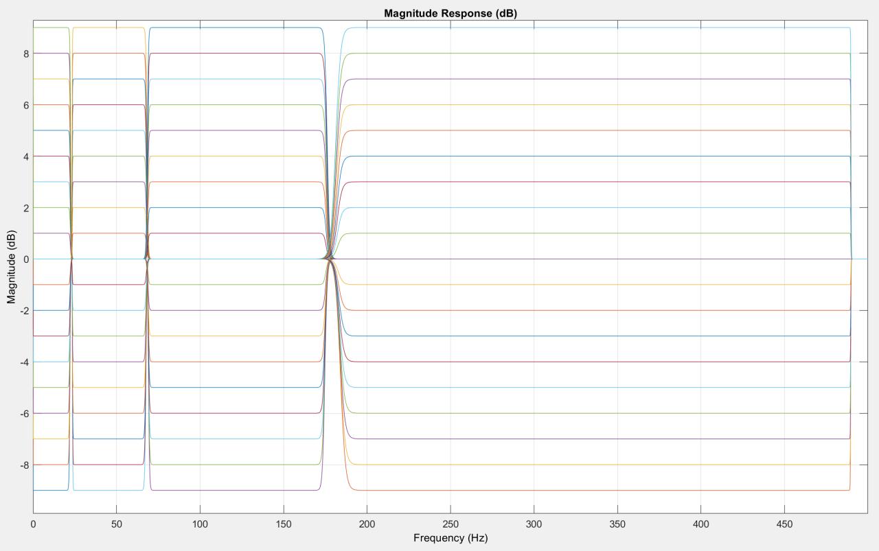
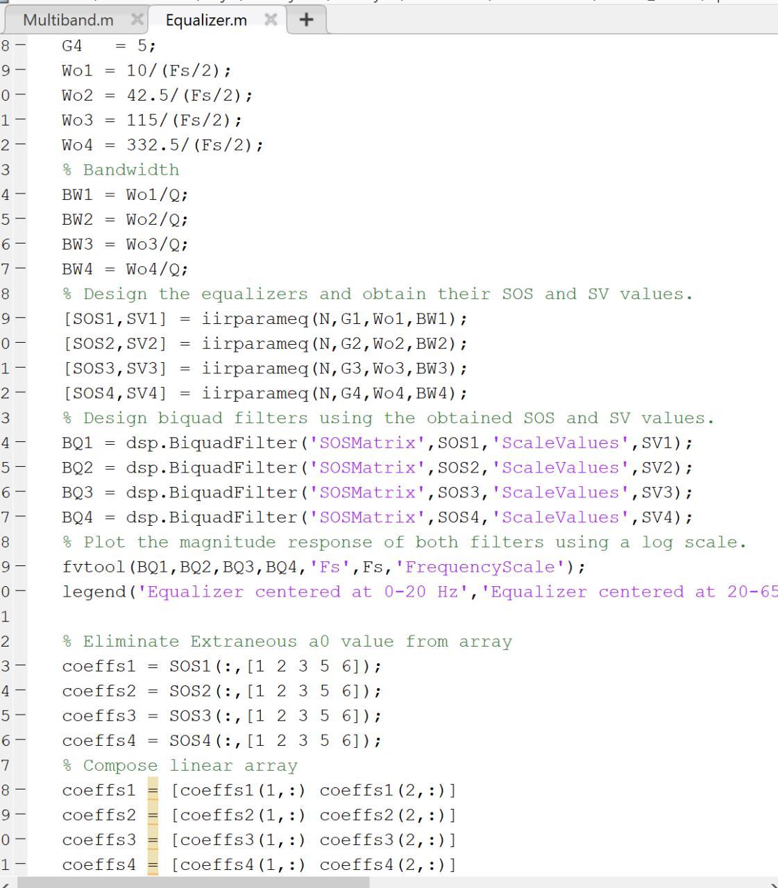
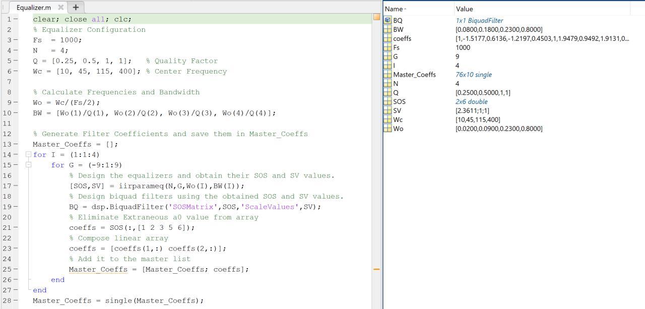
I developed a Matlab script to generate IIR filters specific to the frequency bands I wanted to target, automated the coefficient generation for each gain level (-9 to 9dB), and then generated the coefficients into a single precision floating point array exported as a C code. I then stepped through the graphic equalizer example code and replaced data types and functions that referenced fixed point values with their equivalents in single precision floats and removed unnecessary conversions. I ended up consulting Brandon Stafford for a few minutes since he has more experience with embedded solutions, and we were able to make sense of some vague code.
I will try to adopt this into my main code next week. This took me a little longer than expected, but I’m nearly there. I am curious if I can hack together code from another STM32 example project to display the input and output signals and FFTs on the screen to demonstrate the affect of the filtering – it’s a low priority, but a fun one.
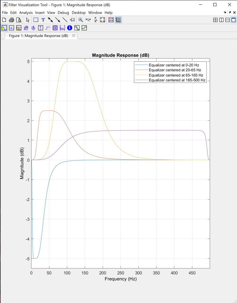
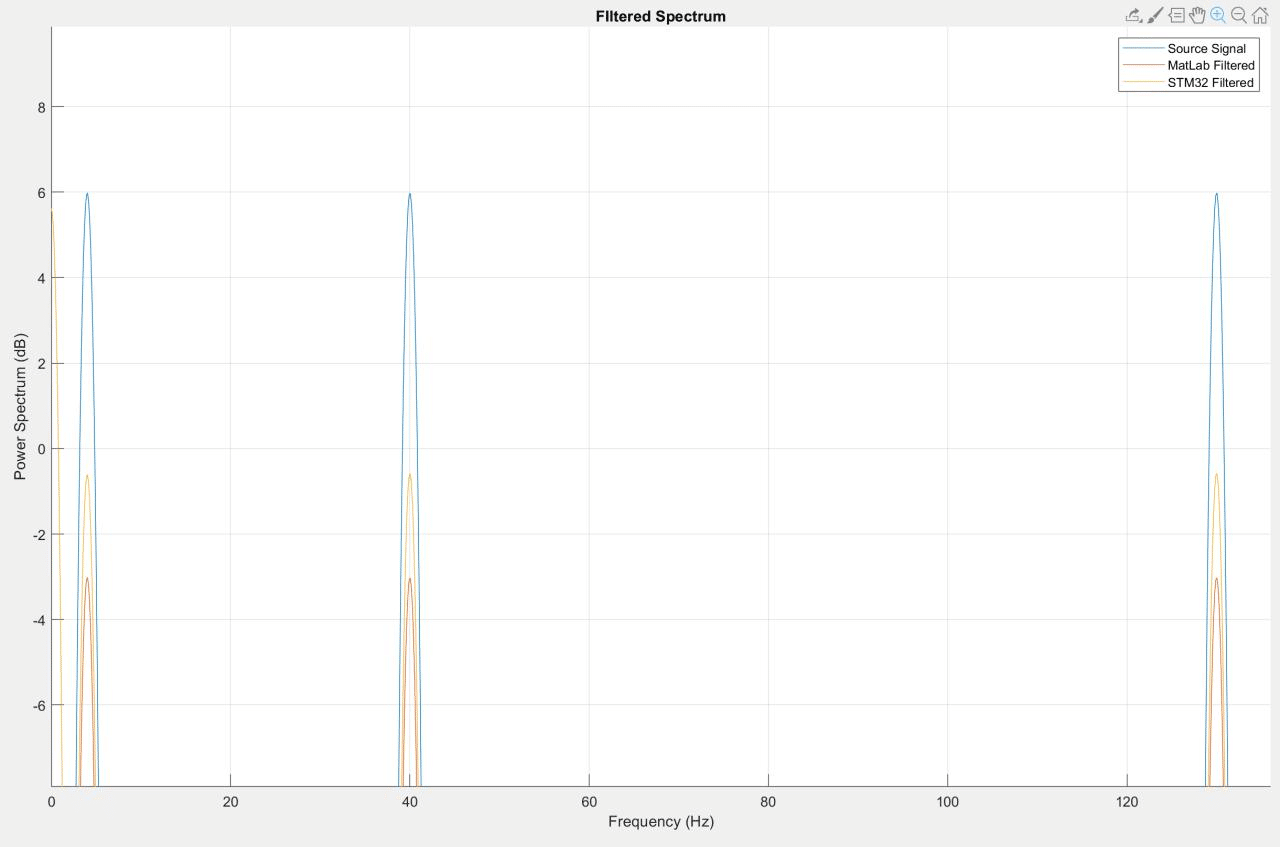
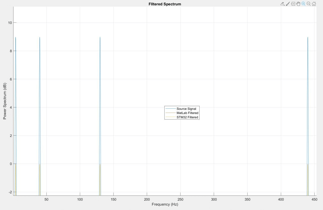
I managed to beat the learning curve associated with the transition to the 32bit STM32 ARM processor. Prior to leaving for spring break, the 50 and 60 Hz filters were confirmed working and good. I have since been working on implementing a graphic equalizer to tune the signal for different users. Using this example in the Keil IDE CMSIS documentation, I successfully implemented a series of single precision floating point digital filters (See Figures 1-3).
I previously developed a Matlab script to generate IIR filters specific to the frequency bands I wanted to target, automated the coefficient generation for each gain level (-9 to 9dB), and then generated the coefficients into a single precision floating point array exported as a C code. This script featured a serious bug that I spent my break chasing down.
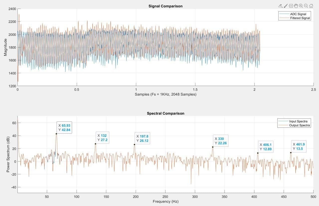
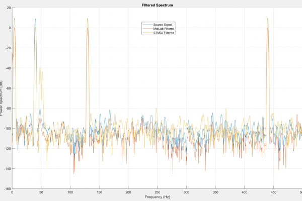
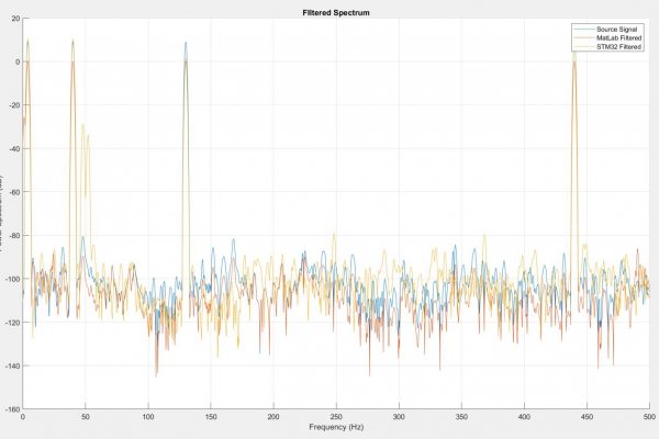
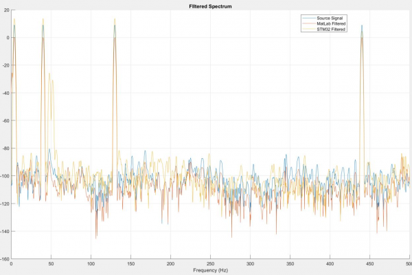
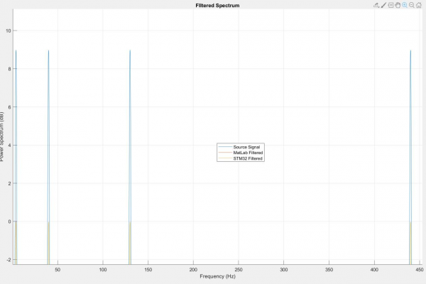
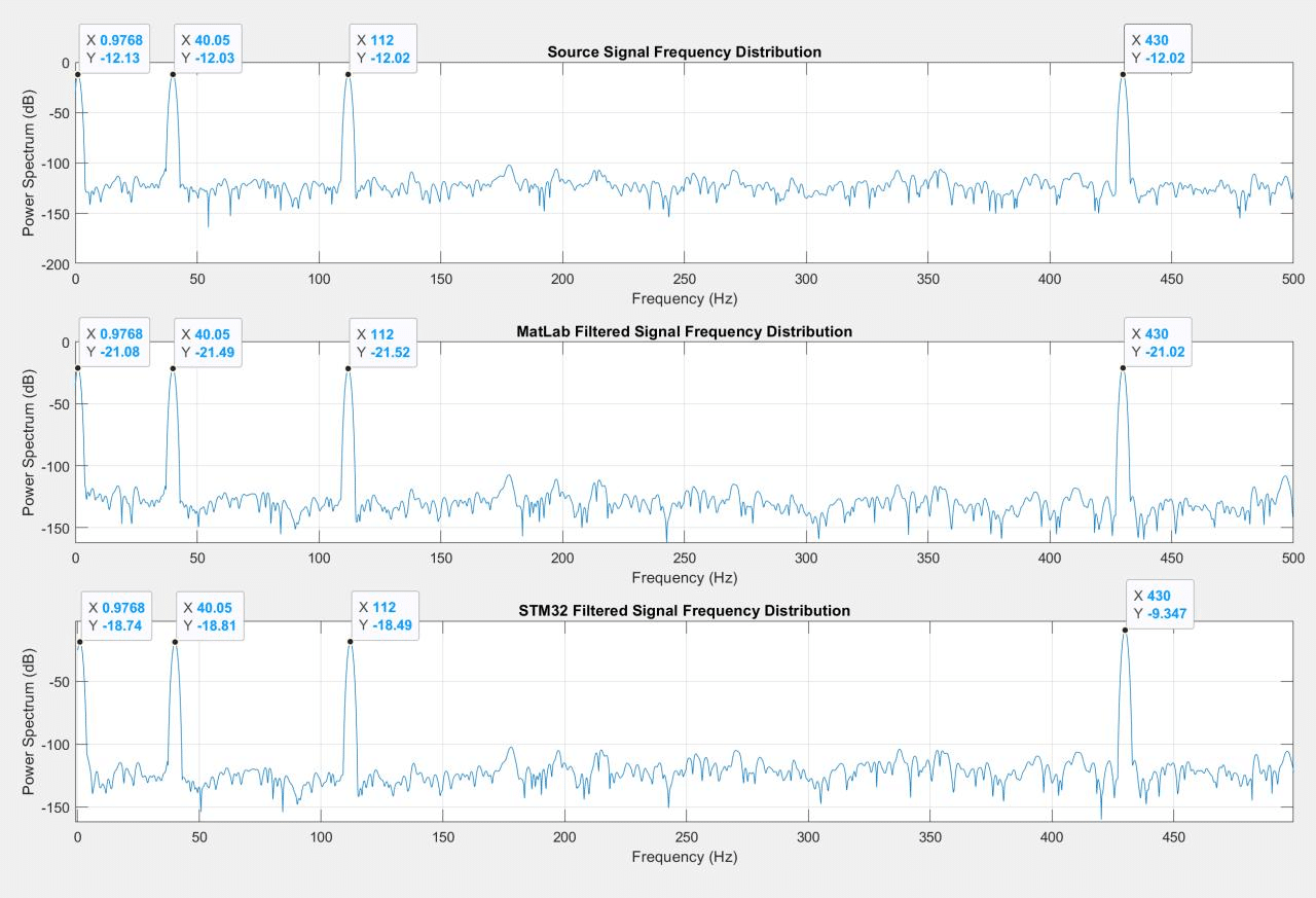
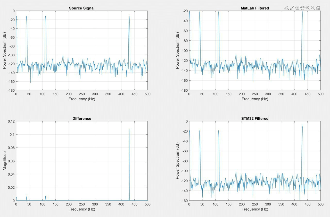
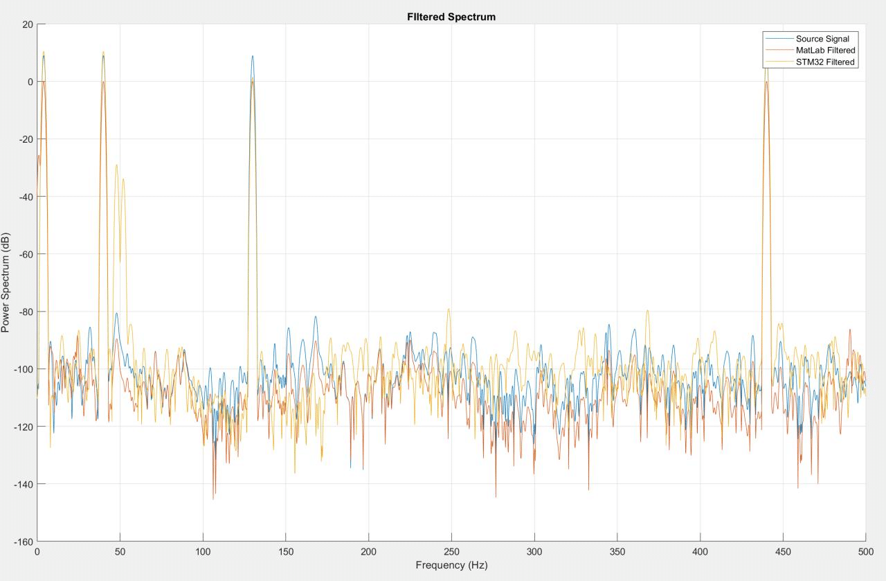
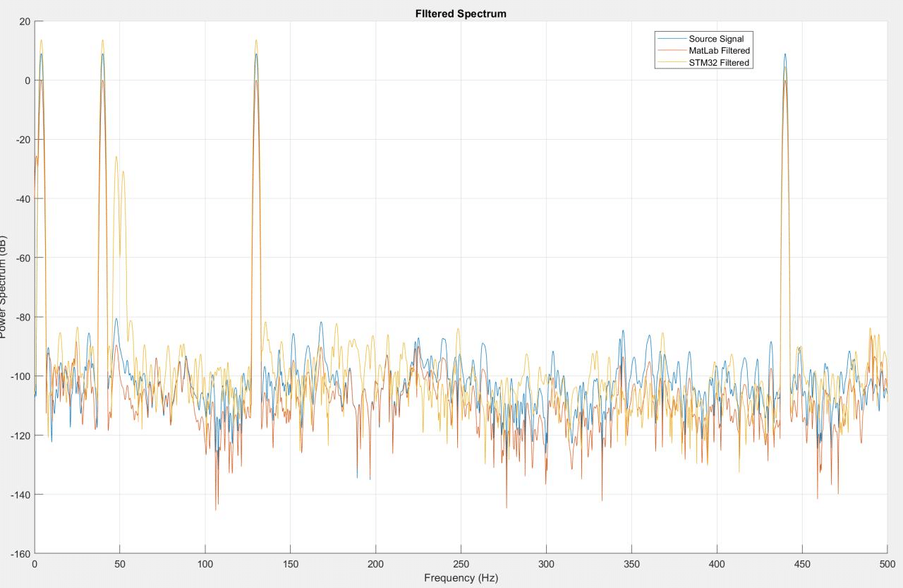
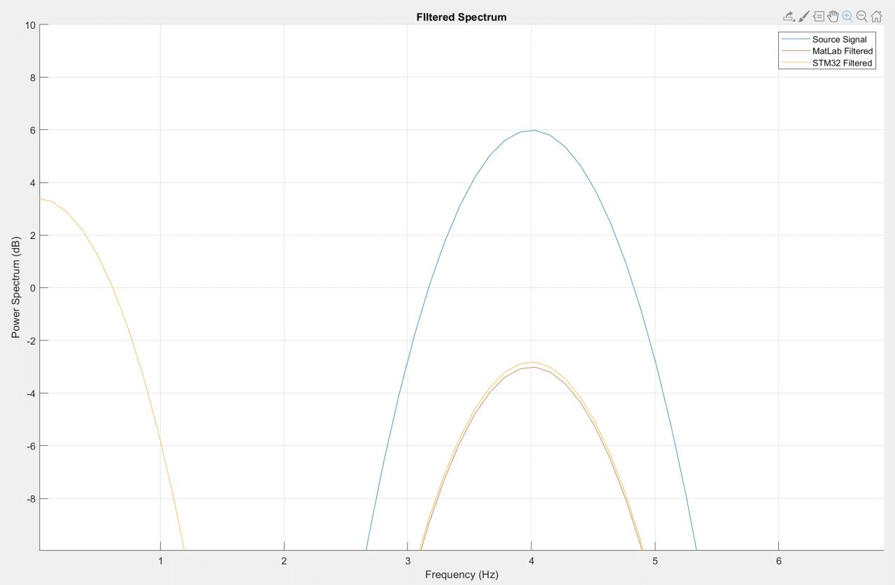
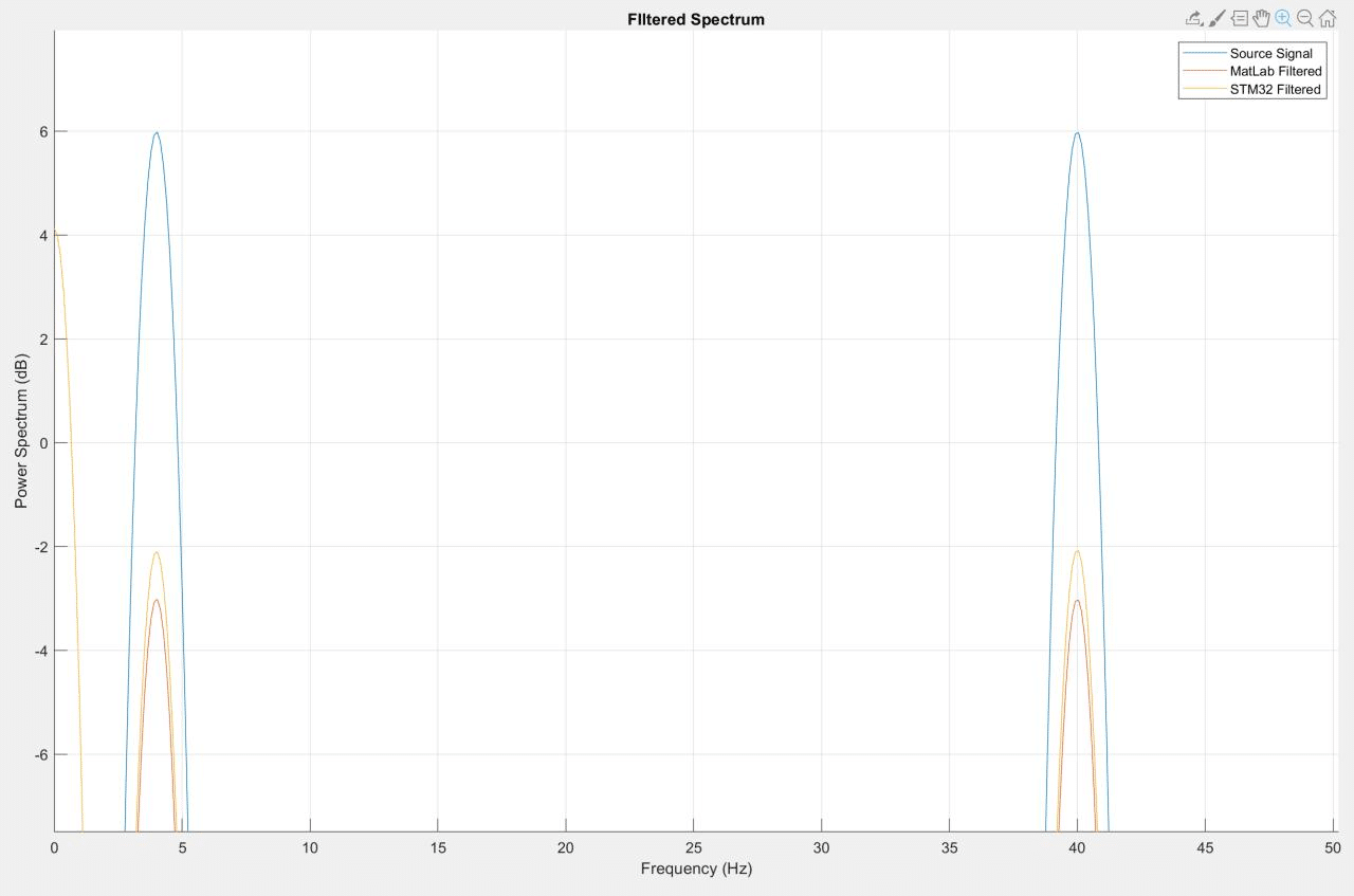
To verify the implemented filters, I generated a test signal and passed it through the filter in MatLab and on the microcontroller. The STM32Cube Integrated Development Environment allows me to access and export specific areas of the microcontroller’s memory (See Figure 4). I copied the filtered signal from the microcontroller and plotted the spectral analysis alongside the MatLab signal. When the gain was set of 0 for all bands, the filter performed identically to the MatLab model (see Figure 5). Encouraged, I tested the attenuation at -9dB across all bands and discovered that the microcontroller signal was deviated significantly from the MatLab signal, indicating a significant difference in code performance (See Figure 6).
The spectra difference initially led me to think that one of the bands was configured incorrectly. I tested the frequency response of each of the four bands and observed that the center frequency of the notches was correct but noted that scale was always slightly off (See Figures 8a-8d). Because the filter’s performance seemed within the margin of error of the MatLab filter performance, I considered the possibility that this was associated with the DSP ROM hardcoded into the microcontroller. I briefly explored the double precision float implementation on the STM32 as a way to bypass the quantization of the filter, but stopped investigating after I discovered that although the STM32 can process 64-bit/double precision floats – it does so very inefficiently. The STM32 handles 32-bit/single precision floats easily and appears to allocate memory for 33-bit values. However, 64-bit floats for double precision are constructed by allocating twice as much memory. This doubles the pointer memory and begins to make clean operations more convoluted in memory – it’s actually a very neat and functional workaround by ST, but is clearly as nuanced as the conversion of double precision floats to fixed point numbers. I left my coefficients as single precision floats and returned to the filter coefficient generation.
By design, filter bands at any gain level should not generate distortion outside of the filter bandwidth. I tested this by setting the gain to zero across all bands and then set band 1, 2, 3, and 4 sequentially to a gain of -9dB (See Figures 9-12). This revealed that the microcontrollers version of bands 3 and 4 generated spectral distortions outside of their bandwidths. This led me to suspect that the MatLab script I wrote featured a significant bug. I revised the microcontroller code to adapt to any filter order and coefficient table size provided and reviewed the MatLab code. I corrected the script to generate coefficient arrays for larger than 10th order and began to step through the data processing in the STM32 memory.
I previously addressed a “MatLab-ism” where digital filter second-order section (SOS) data is formatted as, [b0 b1 b2 a0 -a1 -a2] where a0 is always equal to one whereas microcontrollers expect an array formatted, [b0 b1 b2 a1 a2]. This error was self-evident as the size of the array would be incorrect, but I was looking for a much more subtle error. In all my earlier verification tests, I had observed that the scale of the STM32 spectra differed from the scale of the MatLab spectra. The function I used to create filters from my parameters generated a SOS array and Scale Vector (Gain, denoted as SV in code) array. Although the MatLab DSP filter object accepted both arguments, my script only used the SOS array to synthesize the coefficient table. The question now became how to apply the SV array to the SOS array. Through trial and error, I discovered that removing the last coefficient in the array made it possible to multiply the rows of the SOS array by the column of values in the SV array. However, only the numerator elements of the transfer function (elements denoted as b*) were to be multiplied. The difference between the MatLab and microcontroller execution of the equalizer are now between 10^-6 and 10^-24 (See Figure 13).
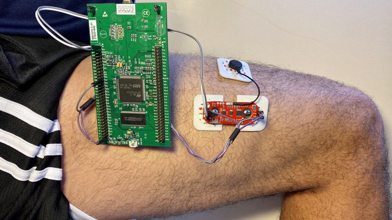
With the powerline filter and equalizer functional, I enabled the ADC sampling from the analog front-end EMG sensor. The code is configured such that data is written to a buffer until full when the filtering process then conditions the data. A serious constraint of this current execution is that the tasks occur sequentially on the same thread: 1ms of recording followed by processing, output not yet included. A clear requirement is now the implementation of threaded tasks. From my experience with the MSP430 series microcontrollers, I can delegate the system to two threaded tasks: (1) analog sampling and transfer to one of two buffers and (2) processing of the most recently filled buffer followed by DAC output.
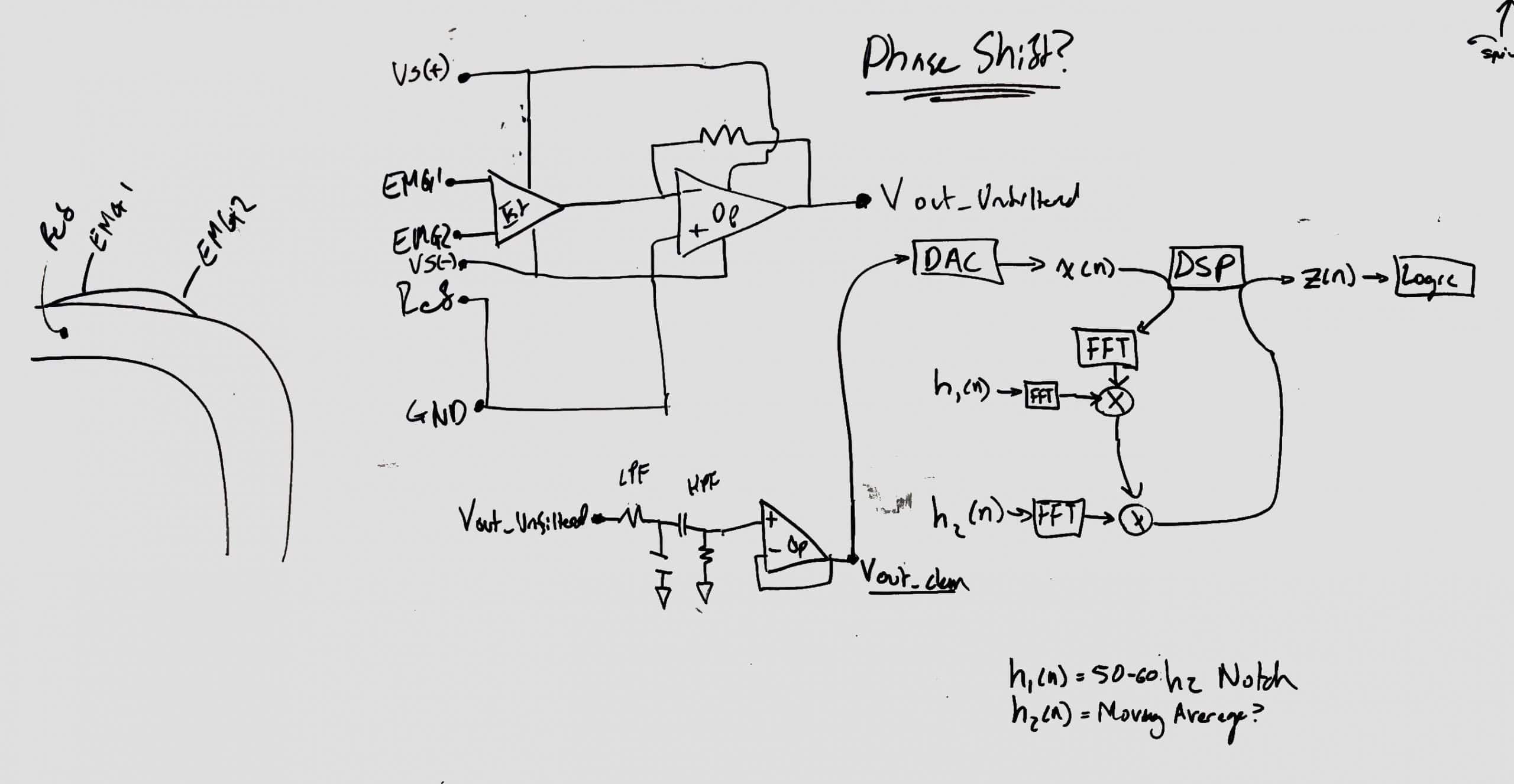
Group delays are a side effect of feedback-based filtering. This phenomena is the result of time delays associated with signals of specific frequencies passing through filter, producing time shifted output. The most direct way to correct this problem is to reverse the filtered signal and pass it through the filter again. This has the affect of applying the specified gain or attenuation a second time and “undoes” the original phase shift. This method, referred to as Zero-Phase filtering, is actually implemented in a commonly used MatLab DSP function named, “filtfilt.” Signals processed in this manner will be in phase with the source signal. An interesting benefit to realizing this feature is that the order of all filters can be reduced by a factor of 2, thereby reducing the total number of hard-coded coefficients stored in the flash and reducing access and processing time.
I previously mentioned the task of separating the sampling and filtering tasks and threading them to run simultaneously to produce a stream of data with minor latency between sensor input and filtered output. This approach is based on my experience with dual core, low-power radio MCUs such as the Texas Instruments CC2650 MODA and Espressif ESP32-WROOM-32. Exploring the implementation of a circular buffer in the Texas Instruments microcontroller DSP SDK manual was enlightening as the small 16 MHz processor demonstrated fascinating workarounds to reduce CPU consumption during DSP operations. Rather than instructing the CPU to request and copy values stored in the ADC buffer, some example code effectively pipes the ADC buffer directly into the first filter. This eliminates an entire copy step and improves workflow and memory usage. This helped me grasp the more powerful solution integrated into the STM32 microcontroller package.
The STM32F429 features two dedicated DMA controllers (Direct Memory Access) which are sectors of silicon dedicated to taking control of the system bus and facilitating data transfer from peripheral interfaces like the ADC to memory without relying on the CPU. When correctly implemented, data sampled from the ADC can be recorded into a buffer which is transferred directly to the microcontroller’s memory without interrupting the CPU’s current task (filtering). There are several modes to choose from depending on the peripheral and data transfer needs. Based on the desire for reduced latency, “direct” transfers from the ADC to RAM make sense. A circular buffer of double length is simultaneously accessed by the CPU and DMA controller. Separate pointers indicate the starting position of each region of the buffer and are swapped when the DMA fills a buffer. The DMA interrupt for completing a transfer will initiate CPU filtering on the newly filled region of the buffer while the DMA controller continues to transfers data to the region that occupied input values that have already been filtered (no interruptions!). This is exceptionally memory and CPU efficient and circumvents the need for task threading by relying on interrupts and silicon!
DAC Configuration
-
-
- Rather than outputting PWM signals based on the total power intensity of the signal, I decided to try to use the STM32’s built in Digital Analog Converter to produce a true analog output. This is not necessarily the most practical way to present the signal output, but I am excited to try to use the hardware through code. The DAC outputs the filtered data at the same sampling rate.
-
Previously I wrote that the oDrive controller will sample a PWM signal from the DSP unit. This is no longer the case. I will output a true analog signal from the STM32’s onboard DAC. I have only used DAC’s through I2S sound interfaces, so this is a bit of a fun adventure for me. It operates on the same 1kHz timer I configured for the ADC.
After the aforementioned tasks are threaded so that the signal acquisition/processing is nearly instantaneous (latency of several milliseconds), I will develop one of two throttle interfaces: (1) the motor controller integrates the DAC output to approximate flexion intensity or (2) integration occurs on the DSP microcontroller. Regardless of the method, this intensity value is fed to a throttle ramp function to smooth the actuator motion.
Last update fixed serious bugs with the MatLab script for generating filter coefficients. I also enabled ADC sampling and DAC output. A flaw in my code for conditioning the filtered output for the 12-bit DAC has come to my attention. I preemptively implemented a scaling function on the filtered data to scale all values to the 0-4095 value range to prevent oversaturation of the 12-bit DAC. Although this handles oversaturation cases, it has the side effect of dramatically scaling quiet signals to occupy the whole value spectrum from 0-4095. I have commented out this code for the time being – a more in-depth method such as a moving average may be helpful and can be elegantly implemented with DSP!
(Continued in EMG to Motor Controller Interface).
The integration of the filtered signal for flexion-intensity will occur on the STM32 microcontroller. The elimination of the CPU’s role in ADC transfers (via DMA controller) provides ample time for the operation. I considered passing the integrated intensity values via PWM duty cycle or UART value to the motor controller’s throttle ramp function. I believe a more elegant solution is to increase the time between filtering operations (defined by the DMA copy completion interrupt that calls the filter function) to provide the opportunity to integrate a customizable throttle ramp into the STM32 firmware. This can be done simply by increasing the buffer lengths. A STM32F429I is capable of acquiring and processing data from multiple EMG muscle sensors, calculating the appropriate throttle value from a ramp function, and performing the phase commutation currently performed by a dedicated STM32 processor embedded in the motor controller. A long-term benefit of this vertical integration is the simplification of the bill of materials and associated ease of software updates, configuration, and diagnostics. Relying on many, underutilized processors will cost more power and money than depending on a smaller number of powerful processors with low to moderate utilization.
Virtual Serial COM
I initialized a virtual serial port on the microcontroller to streamline the debugging process. Previously, to visualize and inspect values, I would copy them directly from the microcontroller memory through the IDE’s debugger. I failed to read the STM32 documentation fully and assigned myself a lot of extra work by assuming that my developer board (v1) was unable to provide UART over USB which is a known and documented limitation of the v0 developer board. I devised a workaround that involved a basic serial to USB converter function running on an Arduino that communicated with the serial port on the STM32. I reassigned my ADC Pin to liberate the PA2 pin to use for this procedure and spent the better half of an afternoon trying to correct any estranged assignments as a result. I eventually read the fine print regarding the developer boards and reconfigured the system to take advantage of the USB UART. ADC input values and filtered output values are streamed over UART in pairs and can be observed in serial plotters. Serial output was originally a low priority task; however I was motivated by a desire to prepare for implementing zero-phase filtering.
Hardware Developments
- STm32F4, 180 Mhz ARM Cortex-M4 Processor.
- Phase-Locked Loop (PLL) for accurate clock speed.
- ARM CMSIS Abstraction Layer
- DSP Hardware
- Direct Memory Access Hardware
Input/Output Developments
- Serial Output (1152000 Baud)
- ADC (1 kHz, 12-bit)
- DAC (1 kHz, 12-bit)
Processing Developments
- 50 Hz Power Filter
- 60 Hz Power Filter
- 4-Band Graphic Equalizer


Revision 1 – Texas Instruments MSP430FR5994
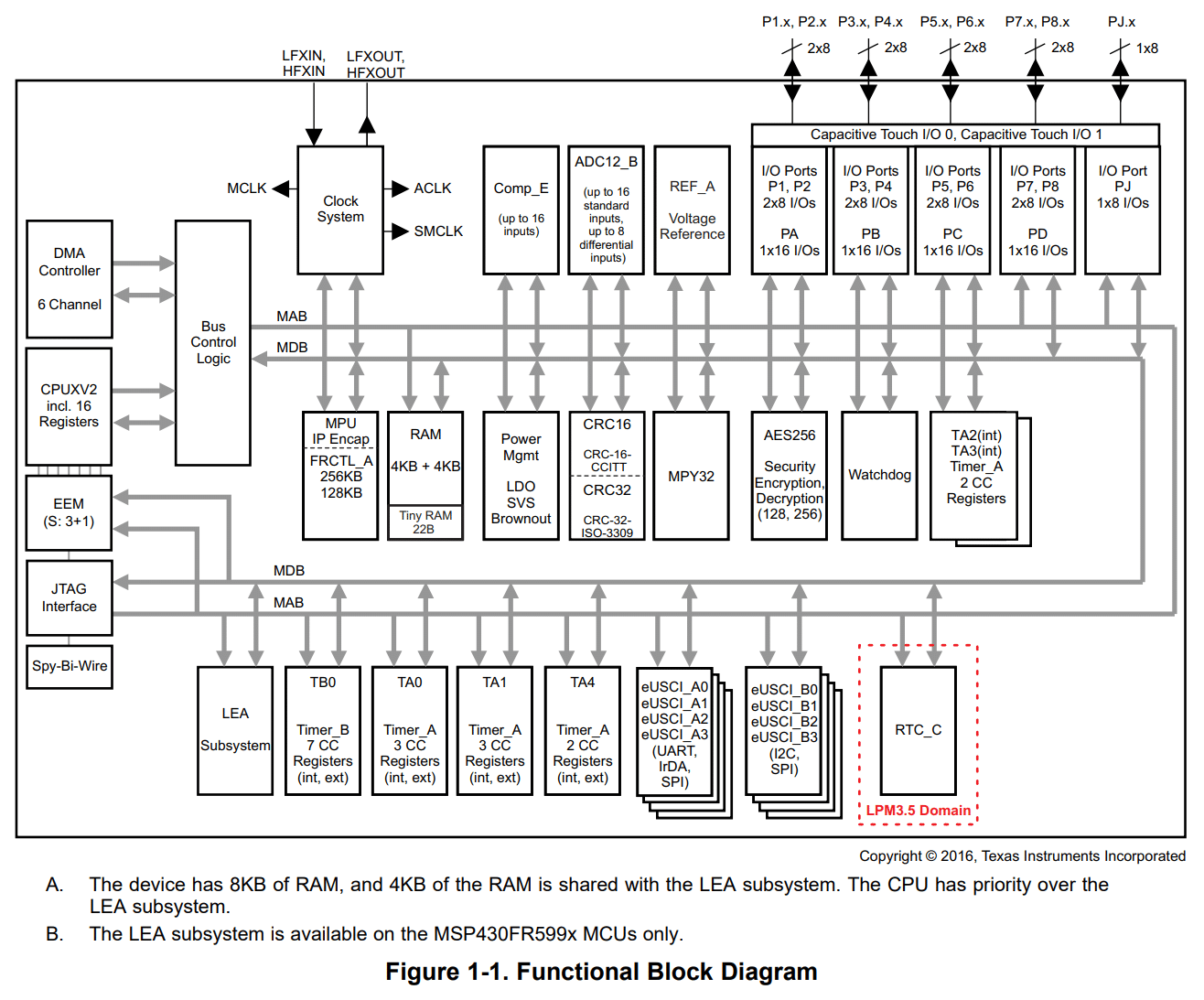
Now armed with the MSP430FR5994, development should be a breeze since all Texas Instruments MSPDSP Library examples are written for this microcontroller. Things looked like they were getting better until I started looking more closely at the actual processor performance.
Analog Digital Converter Update!
Like the MSP430G2553, the analog input range of the MSP430FR5994 is 0 to 3.0V. Although both microcontrollers are limited to an effective linear range of voltage of 2.5V still, the 12-bit ADC really makes an impact as the previous limit of 853/1024 distinct values between 0 and 2.5V is now 3,413/4096. That is a significant bump in resolution and should be more than sufficient.
Computational Problems
Although the MSP430FR5994 and MSP430G2553 operate at the same maximum speed of 16MHz, I noticed inconsistencies in the timer interrupts. Originally, I thought that my voltage supply was defective and causing the clock-speed to dip since it is tied directly to supply voltage. After verifying that my 3.3V rail was stable, I placed additional ceramic capacitors as phsycally close to the VCC pins as possible to further stabilize the power supply. Considering that the power supply was provided by a low dropout regulator with good efficiency and higher current rating than needed, I began to suspect the chip itself was defective.
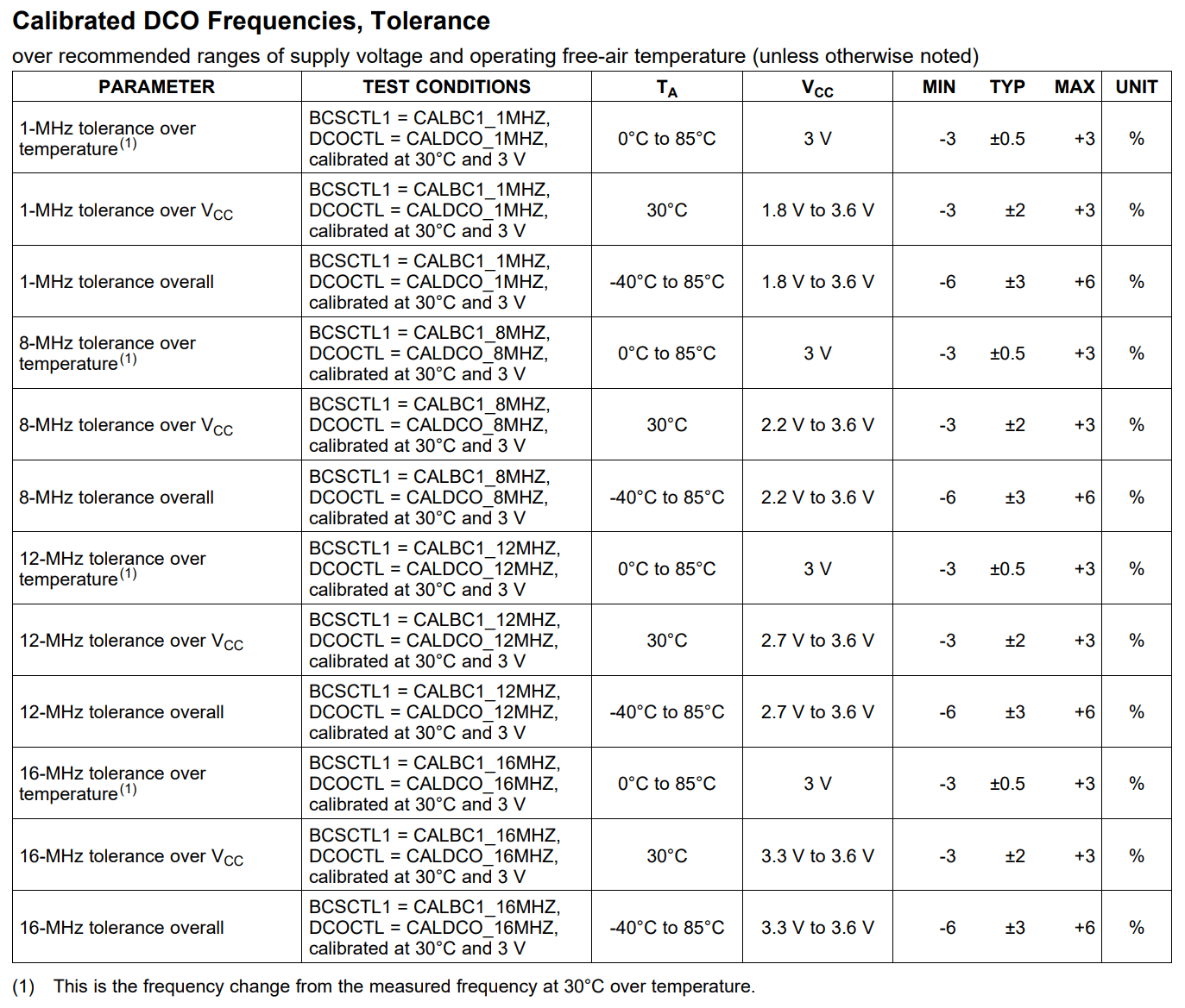
Instead, the problem is the result of a 6% inaccuracy in the clock speed of the MSP430 family. This is a limitation in the silicon design and quality control of the chips. This master clock instability affects computation speed and the ADC sampling rate. The specified 1000 Hz sampling frequency could vary between 940 to 1060 Hz and I might not have noticed.
The main clock crystal inside this MCU is not actually accurate enough to use in final project designs. It is there for convenience during testing and development because providing an external clock is extra cost and generally does not matter when prototyping. While this could be solved by adding an additional crystal and using a feedback loop to ensure accuracy, the effort required to assemble and test the circuit seemed unworthy of the challenge.
Conclusion
Once more, I am stuck with a board that’s good enough to get started, but features a design defect. At this point, I consulted with friend about my options and was immediately recommended the STM32F429I development kit. It features a stable clock, high resolution ADC and DAC, and dedicated DSP hardware. Seems like its worth a shot!
Revision 0 – Texas Instruments MSP430G2553
I ordered the MSP430G2553 microcontroller because it is supported by the Texas Instruments MSPDSP Library. Upon closer inspection of the example code provided by Texas Instrument, I discovered that all example code was written for a slightly different MCU within the same family (MSP430FR5994). I did not expect that this would be a problem as compiling for a different target chip within the same family is not uncommon or difficult. However, the extent of the differences became apparent very quickly.
Challenges
I was able to configure the example code to compile the code originally written for the MSP430FR5994 for the MSP430G2553 I had purchased, but the process led me to some serious design short-sights:
Analog Digital Converter Discoveries
The MSP430G2553, unlike its higher performing siblings, is limited to 10-bit ADC. This defines the immediate limitation of quantizing a detailed, analog signal into 1024 different values. From previous experiences working with analog sensors, I programmed the ADC to use the internal analog reference voltage of 2.5V (1.5V or 2.5V can be provided internally or supplied externally). However, I discovered that the linear range of the ADC was no longer 0-3.0V, but instead 0-2.5V. These oversights compound, resulting in a total 853 reliable values out of 1024.
Floating Point Woes
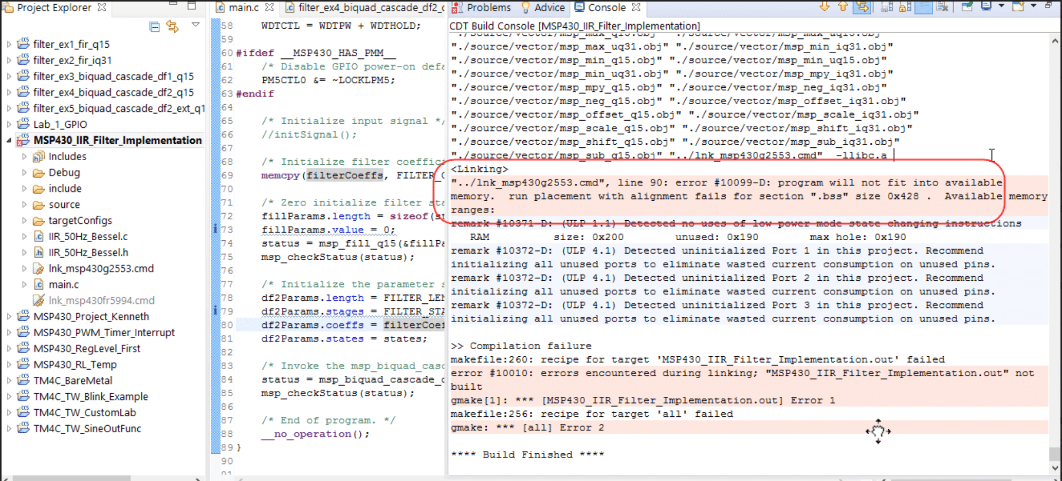
The MSP430G2553 also lacks a floating-point unit for processing non-integer values. The solution to this problem is to use fixed point values, but I am aware of the quantization errors that this can incur both at a data value and filter performance level. By the time I managed to work around the floating-point problem, each compile generated a LOW SPACE ERROR.
Digital Signal Processing Implementation
Values acquired from the ADC are stored in a double-length, circular buffer in the MCU memory. The benefits of implementing digital signal processing over an equivalent analog circuit are very clear from a power saving (eliminating op-amps), configurability (digital coefficients vs analog components), and feature expansion perspective. I expect -65dB of attenuation at 50 and 60 Hz with my current IIR filter (up to -200 dB is possible but would consume too much cycle time to be practical with additional FIR filters) with a weak processor. My FIR filter is designed to scale the remaining 0-500 Hz frequency distribution to amplify the action potential of major muscle groups while minimize contributions such as electrode motion (0-20 Hz). The placement of electrodes and individual action potential frequency response of a healthy adult features a lot of variation I am not able to account for in this design. But I am inspired by Apples demonstration of adaptive DSP techniques on devices low power devices (Airpod Pros). Perhaps a future where the DSP tunes itself is not so far off.
Conclusion
This is the end of the line for this particular processor.
Hardware Developments
- Upgrading from MSP430FR5994 to STM32F4329I Processor
Upgrading from MSP430G2553 to MSP430FR5994
Input/Output Developments
ADC (1 kHz, 10-bit)- ADC (1 kHz, 12-bit)
- DAC (1 kHz, 12-bit)
Processing Developments
- 50 Hz Power Filter
- 60 Hz Power Filter
- 2-Band Graphic Equalizer


")
")
Concept – EMG and Processing
Designing controls for complex machines is a challenging exercise in human factors. Controls and navigation in an exoskeleton should be fluent, low latency, and require a minimum level of training to master. StrydSense™ focuses on delivering an intuitive interface by translating bioelectric muscle signals recorded with a non-invasive galvanic sensor into control signals.
Conceptual Overview
Signal Source: Muscles
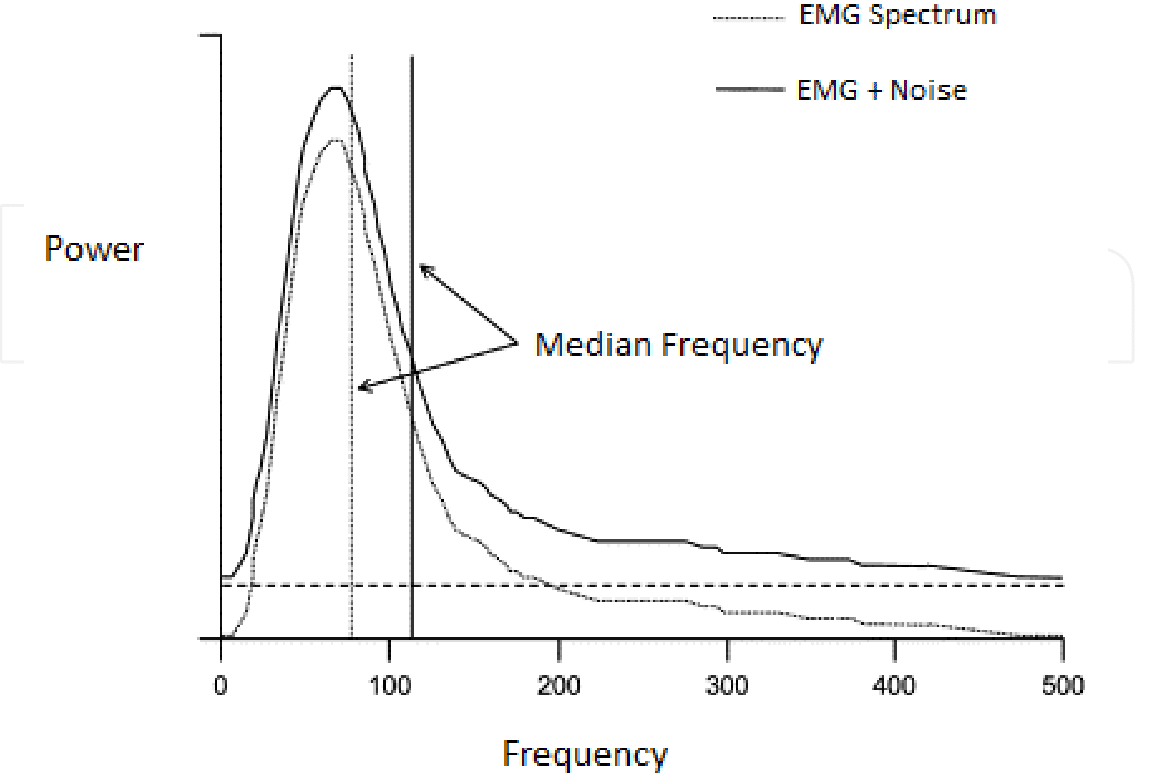
Bioelectric signals are generated in the muscle groups. EMG signal spectra occupy a range of 1-10 mV with a spectra of 0-500 Hz. This is textbook information, so I won’t go too much further in depth. Important regions of the 0-500 Hz spectra can be attributed to specific sources:
- 0-20 Hz: Electrode Motion
- 50 & 60 Hz: Power-line Interference
- 50-150 Hz: EMG Signal Contributions
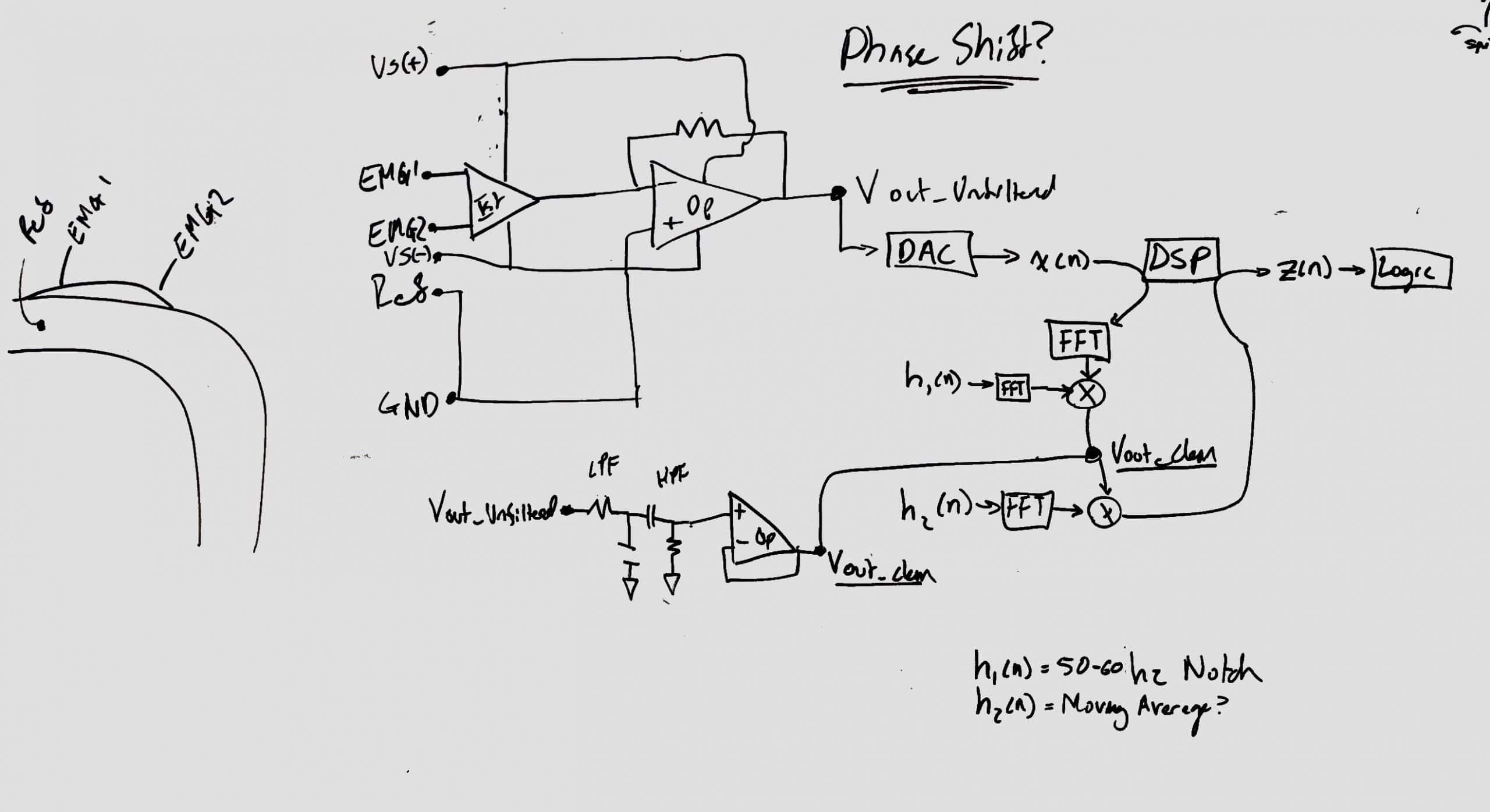
Instrument: Bipolar Electromyogram Analog-Front-End (EMG AFE)
Due to the scale of these bioelectric signals, significant amplification is required to acquire and quantize these impulses with an Analog to Digital Converter (ADC). An electromyogram (EMG) instrument features instrumentation and operational amplifiers that acquire input from electrodes connected across a muscle group through differential amplification. In a barebones EMG circuit, as depicted below, the skin electrodes are connected to the non-inverting instrumentation amplifier inputs. Signals common to both electrodes are attenuated by connecting the inverting outputs of both amplifiers to the amplifier output. This negative feedback loop helps isolate EMG noise from signals common to both inputs such as capacitively coupled AC powerline noise. The final amplifier is used to scale the output of the instrumentation amplifier to fall within the majority of the ADC range and mitigate saturation.
<Graphic EMG>
Signal Acquisition: Analog-Digital-Converter
The continuous-time analog signal produced by the Analog-Front-End is quantized into discrete-time digital values by hardware integrated into the microcontroller. At a high level, the Analog-Digital-Converter (ADC) acquires a data point within a range defined by the bit-rate at an interval defined by the sampling frequency. At a low lever, the ADC is a timer-interrupt based device that measures the analog signal potential relative to the processors power input. The ADC can be configured to use a highly stable internal reference voltage to improve the accuracy of the data point. A timer based on the processor’s master clock is configured to generate a signal at precise and accurate intervals which triggers the conversion and transfer of data to microcontroller RAM.
<ADC System Clock>
Although the bit-rate and sampling frequency are dependent upon the microcontrollers integrated hardware and performance, the sampling frequency can be specified using the Nyquist–Shannon Theorem. A minimum number of data points per second are required to represent a continuous-time signal with discrete-time data. The minimum required sampling rate, Fs, is defined as twice the magnitude of the highest frequency component of interest. For a EMG spectra with a maximum frequency of 500 Hz, the sampling frequency must be a minimum of 1000 Hz.
<Signal Representation/Sampling>
Sampling frequencies above this threshold increase the maximum frequency that can be recreated accurately and provide additional resolution to the threshold already accurately represented. Analog anti-aliasing filters limit the propagation of signals higher than the Nyquist frequency from entering the input of the ADC to prevent signal distortion. In audio applications, digital filters can be applied to achieve a similar effect without the need for physical hardware.
Digital Signal Processing: Filtering and Post-Processing
The discrete-time, digital representations of the EMG signal stored in RAM are processed through digital filters to condition the signal data. First powerline interference (50/60 Hz) is removed, also attenuating higher degree harmonics. Second, a filter shall help scale the frequency contributions to highlight EMG signals. I will focus on briefly describing Infinite Input Response (IIR) Filters and Finite Input Response (FIR) Filters because it is not possible to meaningfully summarize digital filter design and techniques which are the subject of EE-125.
An IIR filter and FIR filter differ significantly in procedure. A FIR filter is applied to a data set without recursion whereas an IIR filter features feedback to achieve a higher degree of attenuation. The most pertinent design concerns are memory/processor usage, filter stability, and distortion. FIR filters require memory proportional to the data being processed and are stable with linear phase when designed correctly. IIR filters have considerably lower memory/processor requirements but can be unstable and introduce time distortion. I have not implemented any digital filter more advanced than a moving-average filter on a microcontroller and my challenge will be to functionalize it to the extent I can.
Motor Control: Signal Intensity
By integrating the total signal intensity for given intervals, I can generate output PWM duty cycles proportional to the magnitude of muscular flexion intensity.
Methods
Software Design:
I proposed a 50 and 60 Hz Power line filter designed as IIR filters to maximize the degree of attenuation without significantly increasing processor usage. I also propose the use of a FIR filter to scale the signal spectra associated with electrode motion noise (0-20 Hz) and EMG signal region (50-150 Hz).
I have learned how to design and verify these filters in EE-125 in MatLab, so transferring the designs to microcontrollers will be the primary challenge. Understanding the limitations of the microcontrollers and their configuration is an underlying challenge I hope to overcome.
I have selected the Texas Instruments MSPDSP Library and MSP430 microcontroller family as my starting point because of clear examples provided by TI as well as the capability of running the Texas Instruments MSPDSP library on other hardware. I foresee the immediate challenge wherein the native sampling rate of 125 kHz at 10 or 12-bit resolution on these microcontrollers will quickly consume a great deal of memory and cycle time. These problems may be circumvented with clever pointers and memory usage, but we shall see.
Hardware Plan
- Analog Front End (Designed or Advancer Sensor Kit)
- Texas Instruments MSP430 Microcontroller family
- 10/12-Bit ADC
- oDrive BLDC Motor Driver
Input/Output Plan
- ADC (1 kHz, 12-bit)
- PWM Duty Cycle Output
Processing Plan
- 50 Hz Power-line IIR Filter
- 60 Hz Power-line IIR Filter
- 2-Band FIR Filter
")


